CYLINDRICAL ACOUSTIC SILENCERS (SNVC)
CYLINDRICAL ACOUSTIC SILENCERS (SNVC) FOR DUCT AND FANS
CYLINDRICAL ACOUSTIC SILENCERS (SNVC)
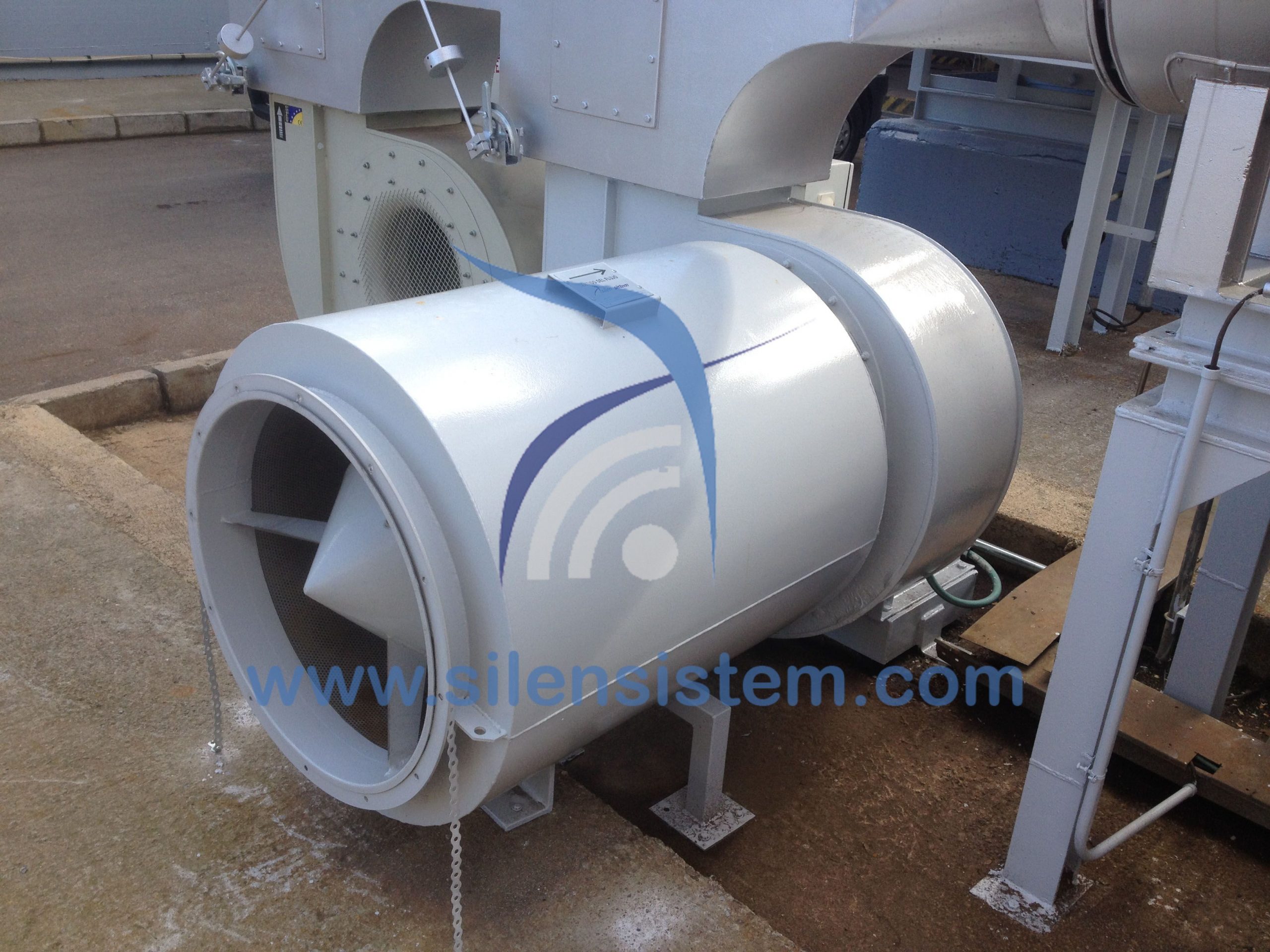
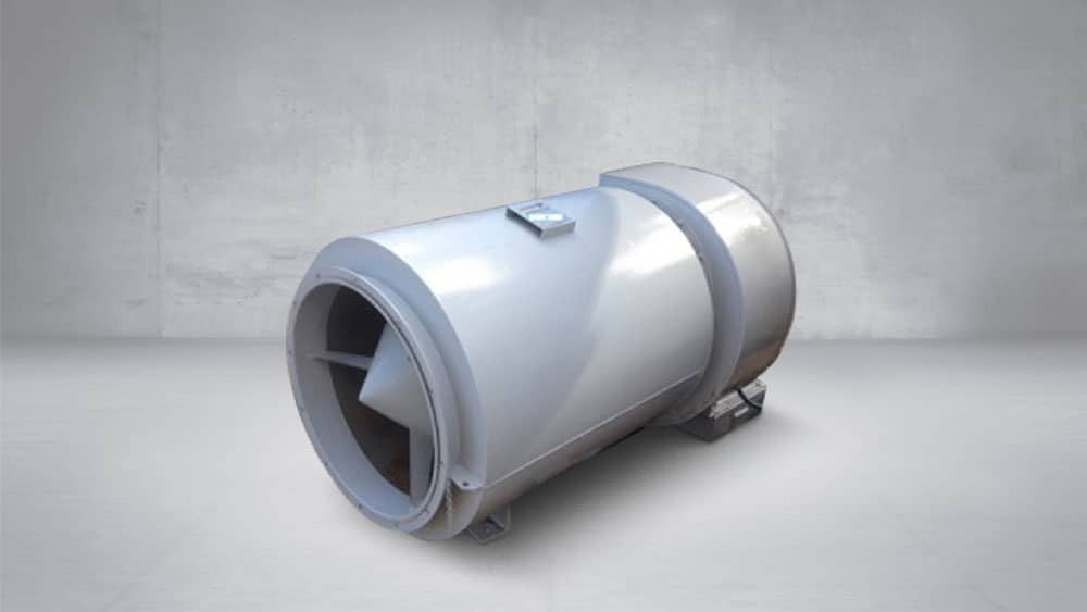
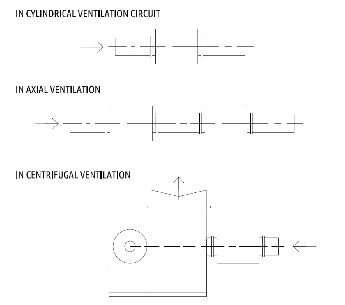
The SNVc range of silencers has been studied for ventilation installations. These silencers are intended to be installed in:
- Aspiration or impulsion of the helical fans.
- Suction or impulsion of centrifugal fans.
- Cylindrical ventilation circuits.
The silencers admit an overpressure of 250 mm AC and a temperature of 100º C. Beyond these limits, please contact us.
DESCRIPTION
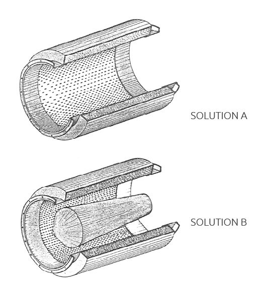
SNVc silencers are of the absorption type. There are two versions:
Solution A: direct weight, provides without increased head loss, a sensible attenuation of the sound level.
Solution B: has the same dimensions and is equipped with an aerodynamically soundproofing element, allowing a much greater acoustic efficiency to be obtained with a limited pressure drop.
MANUFACTURING
The SNVc to 900 silencers are made of galvanized sheet metal. The SNVc 1000 to 1600 silencers have the outer shell of black sheet metal with anti-rust paint and the inner parts of galvanized perforated sheet metal. The silencers are equipped with flanges. The absorbent material is rot-proof, non-hygroscopic and non-flammable fiberglass.
DETERMINATION OF SILENCERS
SNVc silencers are chosen based on the following criteria:
• Acoustic efficiency (table I) and air flow noise (tables I and III).
• Flow and allowable head loss (Table IV).
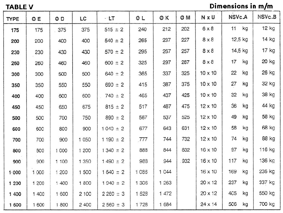
• The dimensions (length and diameter) table V.
The chart above represents the dynamic efficiencies of the SNVc range of silencers. They have been determined based on tests carried out under normal operating conditions after the elimination of parasitic noise. SNVc silencers have been mounted at the end of a duct between a reverberation room and an anechoic chamber. The measured efficiencies correspond to the difference in sound pressure measured in the anechoic chamber with and without a silencer. The choice of efficiency depends on the noise level emitted by the noise source to be soundproofed and on the residual noise level to be obtained.
EFFECTIVENESS
SNVc silencers are installed at the end of a duct located between a reverberation room and an anechoic chamber.
All the measured efficiencies correspond to the sound pressure difference measured in the anechoic chamber with and without a silencer.
The effectiveness depends directly on the sound level emitted by the noise source to be soundproofed and the residual sound level to be obtained.
UTILIZATION
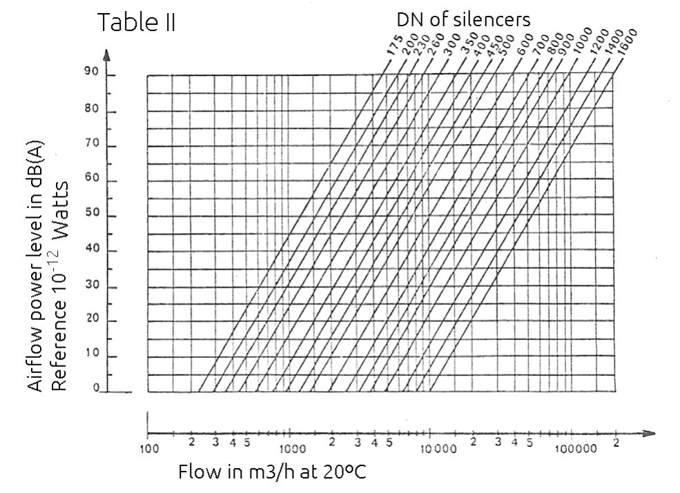
Airflow noise in SNVc silencers limits their attenuation in certain cases. It is therefore necessary to verify for each use that this noise does not compromise the acoustic result you want to achieve. To achieve this, the noise of the air flow must be in each octave band, less than 8 to 10 dBA with respect to the residual sound power spectrum that is to be obtained at the output of the silencers. Table II allows this verification. Determine the approximate overall level A of the sound power created by air circulation in the SNVc silencers: Solution B.
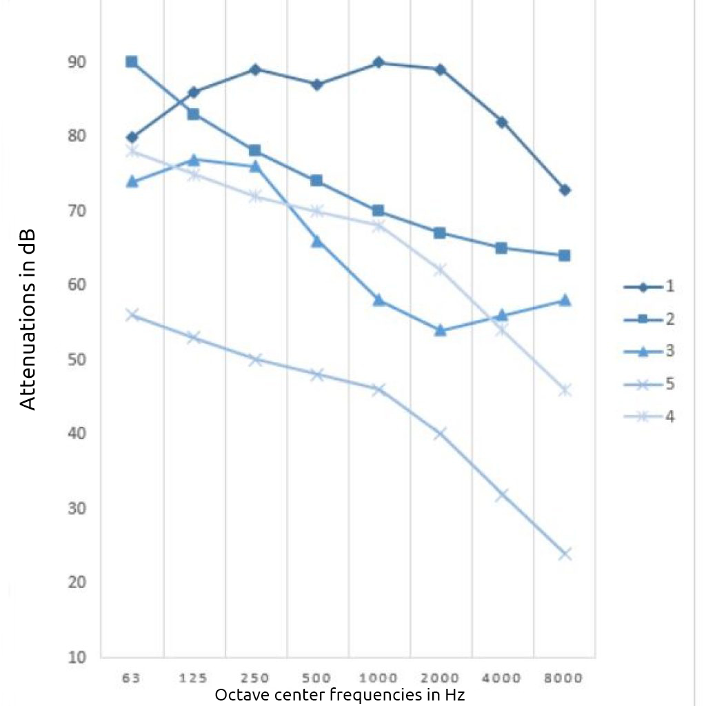
The corresponding spectrum is obtained by adding the value read in «global A» to the corrections defined in Table III.
The noise of the air flow in solution A of the SNVc silencers is equal to that created in a cylindrical duct of equal section.
ASSEMBLY EXAMPLE
For ventilation installations, Silen Sistem also supplies:
- Rectangular silencers.
- Absorbent panels.
- Soundproof hoods for fans.
- Sound insulation of fan and ducts.
- Complete soundproofing of air central.
- Acoustic Engineering and Studies
EXAMPLE
- Centrifugal fan.
- Flow rate: 10000 m2 / h at 20 ° C.
- Allowable pressure drop: 25 mm AC.
- Fan sound power level: 94 dBA.
- Fan sound power spectrum: curve 1.
- Allowable residual sound power spectrum: curve II.
- Residual sound power spectrum with SNVc solution B: curve III.
- Sound power level created by air flow: (see table II).
- Air Flow Sound Power Spectrum with SNVc 600 (curve IV)
-
-
-
-
-
- SNVc 600 = 50 dBA.
- SNVc 600 = 72 dBA.
-
-
-
-

In this case, the noise of the air flow compromises the desired acoustic result.

PRESSURE DROP
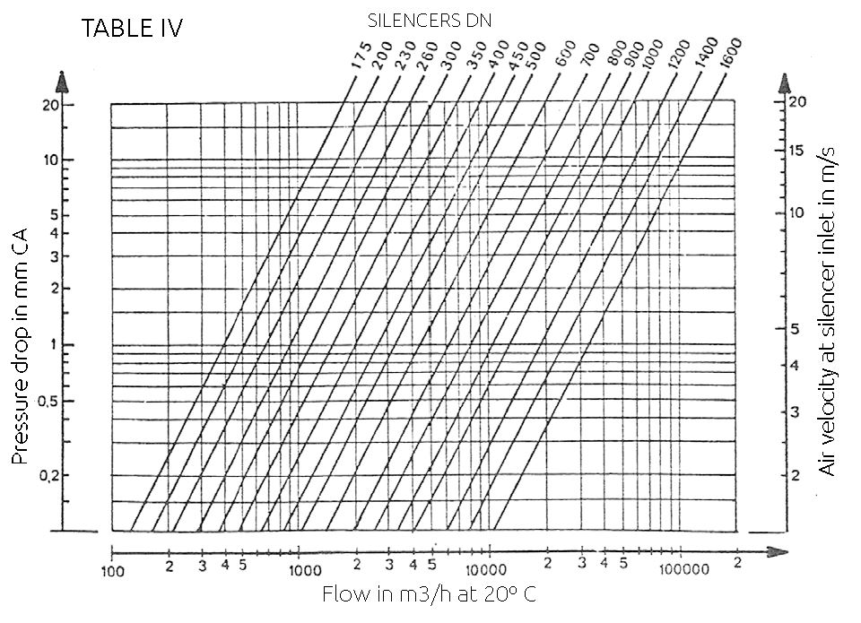
Table IV allows to determine, according to the air flow, the diameter of the adaptation, the pressure drop of the SNVc solution B silencers and the air velocity at the entrance of the SNVc solution A and B silencers.
The pressure drop of «solution A» in SNVc silencers is comparable to that obtained in a pipe of the same length as the silencer. For temperatures much lower than 20 ºC the loss of AP pressure read in table IV has to be corrected.
EXAMPLE
- Axial verification.
- Air flow: 10,000 m2 / h at 20 ºC.
- Fan diameter: 600 mm.
- Allowable pressure drop: 5 mm AC.
- Silencer chosen: SNVc 600 solution B.
- Head loss: 5 mm AC.
- Air speed: 10 m / s.
ACOUSTIC SILENCERS DIMENSIONS
CYLINDRICAL ACOUSTIC SILENCERS (SNVC)
